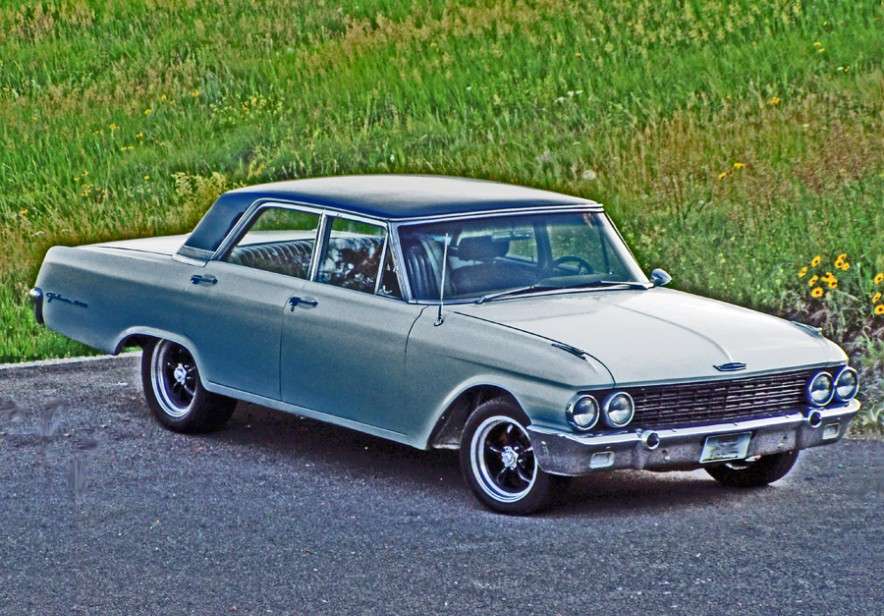
This forum is for all years of the Ford Galaxie and all other Full-size Ford, Lincoln, and Mercury cars. This is a place to share information, skills, pictures, and stories for the purpose of building friendships and furthering the enjoyment and restoration of these cars |
Offline
What I am looking for is all the measurements to basically recreate what you made. I am looking for thicknesses of the materials, dimensions, hole spacing, the more info the better, and a bunch more pictures would be fantastic. I figure why reinvent the wheel Thanks
Offline
I will start by sending you the installation article I was able to get my hands on. Contained in the article are some good pictures of all of the brackets. I will make a few suggestions to help you out...not that I am an expert, just sharing my experience thru trial and error. My first suggestion is to consider trial fitting the rack with wood brackets like I did. It is easy to make changes if you need to. If I was to do over, I would drop the rack a little lower to the ground. I ran into some starter interference and the hard hydraulic lines on the rack were making contact with the bottom of the oil pan. Both issues I had to correct. Also, I would be careful tilting the rack as you were thinking. You may run into a couple of issues: The u joints off the rack might make contact with the factory brake line distribution block and secondly, you may position the outlet for the hydraulic lines for the rack so that they face the inside of the frame rails, so it may be impossible to conect the hydraulic lines to the rack.
Page 1
Page 2
Page 3
The dimensions for the bracket were determined once I had the rack installed, so your bracket might be slightly different. The dimensions were determined to make the tie rods sit in the exact location as per factory, with the exception that they are 1 inch closer together. If you don't do this, the bracket will be too wide and contact the aluminum hydraulic lines on the rack as the bracket travels from side to side when turning the steering wheel. With that being said, I also had to bend the lines slightly, to make clearance for that bracket. With the bracket made the size it is, it gives me two inches 2" of clearance for the tie rods between the rear of the front crossmember and the front side of the offset bracket. I have discovered that the only way to install the tie rods is to mount them to the offset bracket first, mount the bracket to the rack and then install the tie rods onto the spindles. With my engine and tranny combo, there just isn't alot of room available so I don't think I could have really changed anything, other than to lower it slightly. In fact it is so tight, I had to shave the heads of the two bolts that fasten the access plate for the tranny from contacting the accordian boot on the rack during rack travel.
Bracket dimensions:
I started with a piece of 1/4" angle. 7 1/2" total length. Bottom side is 3" deep, front side(tie rod side) 1 3/4" tall.Tie rod pilot holes centers are 3 1/2" apart, and center of holes are 7/8" down from top of bracket. On the tie rod side of bracket I added a 1/2" piece of metal for thickness to allow for enough material to get tapered holes drilled for the tie rods. I added a 1" x 1" block to the back of the bracket where the bolts will go to attach bracket to rack. That was the size I needed to get the tie rods to sit in the correct location and to also allow me to use the OEM bolts from the donor J car I harvested the rack from. The holes for the mounting bolts are 1/2" diameter and hole centers are 2" apart from each other.
I hope this is what you need for dimensions. If I can help further, let me know.
Dan
Offline
Thanks for all the info. I am gearing up to do mine in the next couple of weeks. I will post pix and keep the forum up to date on my progress.
Offline
No worries. Still no answer about the reamer size for the offset bracket...it's still sitting over at the machine shop waiting to get done.
Offline
dan_6776 wrote:
One more problem! I ditched the donor flange that I used to attach to the factory steering flange. Made a new piece by using some flat bar and welding a piece of DD shaft to it and then bolted to the steering flange.
Dan, I was going back through this thread to get any last minute info before I rip into my old Gal, and I saw this post. I am a little concerned about the way you fixed the steering linkage. I have modified/built a lot of things for my cars. I am not an engineer, so I can't calculate the mechanical stress on a part or even begin to know its exact failure point but I can overcome this lack of engineering skill by doing two things, First figure out what seams logically strong enough based on real world experience, intuition and common sense and then use that as a base to make it even stronger than what seams good enough. And second always build in a "fail safe” on any part that failure could have catastrophic consequences. Whenever I am working on a project I try not to rely on welds on any application where a weld failure would cause catastrophic failure. A perfect example of this is the way you built the tie-rod to rack bracket. By using angle iron you made it in such a way that if the welds were to fail everything would still be held together by bolts and or tie-rod ends acting like bolts. (Built in redundancy) I don't see the same redundancy with your connecting flange. If the weld brakes the steering shaft becomes disconnected and you loose the ability to steer, which of course would be catastrophic.
A better option IMHO would be to cut a 3/4" DD shaped hole in a piece of steel (could easily be done with a drill and a hand file) than take a piece of 3/4" bar stock and machine it to be DD (this could be done with a hand file or grinder) but leave a thin 1/8" flange on the end where it is still round. The machined shaft could then be slid into the DD shaped hole in the steal to the point where the flange on the end is flush against the backside of the steel where it could be welded in place. This way if the weld were to fail the DD shapes from the shaft and the hole in the steel would still allow the rotating motion to transfer from the steering column to the steering shaft and the flange on the inside of the mounting bracket would keep the steering adapter from coming apart.
I'm not saying the way you did it will fail. In fact I know that even a small weld when done correctly will be extremely strong. You will probably be good to go with no issues, but if there was a simple solution to make it "fail safe” wouldn’t it make sense to do it that way? I would strongly consider changing the way your adapter is made. If you need more info as to what I have in mind let me know.
Offline
Hi Daze,
Thanks for your thoughts on this. I honestly do appreciate your concern for safety. I also appreciate that you would take the time to review the post and get back to me. I also am not an engineer, so I rely lots on the experience of others to help me as I go.
I also did consider a weld failure when I made that bracket which attaches the u-joint to the steering flange. What I did do is make a hole in the flat bar the same shape and size as the DD shaft with a drill and file. I then extended the DD shaft through the bracket. So on the backside of the bracket(flat bar) which you cannot see in the picture, there is an additional 3/8" inch of DD protruding. I then welded the two together. My thinking was if the weld fails, the DD shaft running thru the bracket could still provide steering because it is running thru a DD shaped hole rather than a round hole and therefore unable to spin freely in the flatbar.
I hope my description makes sense. I also hope you feel that my method does have a type of fail safe measure? If not, I can easily make a change.
And as a follow up, my offset bracket still isn't done. Should be soon. As soon as I get it back, I will post the reamer bit size.
Offline
OK that seams way better than what I thought you had done. The key is the DD hole in the steel plate. The welds should act like the flange I was mentioning so I think you are good to go.
Offline
Hey Dan, I envy you that the engine was out when you started this and that the front sheet metal was off the car. This project is kind of a pain to do, working around the engine, hydroboost, clutch MC fenders and hood. A least I can get under the car with my lift so it could be way worse On your setup, how is the steering shaft support column mounted. I see it goes through a tab that comes up off the frame but how is that tab mounted??
Offline
When doing the mock up, I was thinking how lucky I was that I had all of the room I did with only a frame. However, looking back, with no motor in place to check for clearances, I did run into some contact issues as I previously posted. I'm sure it's a real pain with what you are dealing with, but your not guessing like I had to.
There is a bracket on the inside of the frame that share two of the larger bolts that attach the drivers side rack bracket to the frame. I had to make a couple of brackets until I got the angle right for the rod end bolt.
There is a shot of it in one of my earlier posts.
It would have been easier to have everything connected first, then build a bracket and weld it to the top of the frame rather than the way I did it.
Last edited by dan_6776 (April 9, 2015 10:04 am)
Offline
Today I got the offset bracket back from the machine shop and installed on the car. For the tapered holes to be made a lathe had to be used as the reamer bit wouldn't work due to clearance issues. I now consider this conversion done. The hydraulic lines from the hydroboost are also connected, just need to run return line to oil cooler and back to reservoir.
Tie rods bolted to offset bracket:
Front shot of rack. As you can see it is tucked up nice and high, road clearance won't be an issue, you can hardly even see it from this view.
Side view. You can see how tight the install is. Not much room was available between the rear of the front crossmember and the transmission. That cable you see under the accordian boot is the transmission shifter cable. It actually ran right into the rack from the transmission, so I changed the angle of the cable mount on the transmission to direct the cable just below the rack.