Galaxie Forum Full-size Ford, Lincoln, and Mercury DazeCars www.galaxieforum.com


This forum is for all years of the Ford Galaxie and all other Full-size Ford, Lincoln, and Mercury cars. This is a place to share information, skills, pictures, and stories for the purpose of building friendships and furthering the enjoyment and restoration of these cars

You are not logged in. Would you like to login or register?


March 19, 2013 6:58 pm  #1


hydroboost possible?

Group with the price of a power brake booster for a 64thru the roof, i was wondering if i could use
a hydroboost brake setup from a late 70's lincoln or a newer 2000+ ford.
Anyone?


64 Galaxie Country Sedan Wagon
69 XL Convertible "390" w/ Air
1990 Crown Vic Wagon
 

March 20, 2013 9:08 am  #2


Re: hydroboost possible?

I put hydroboost on my 62.  I made several posts about it on the old forum.  here are some reposts of that info.  some of it is redundant between posts but will give you most of the info

On August 27, 2011, 9:53 pm Daze wrote:

The old Gal is about to get power brakes, but not with a vacuum booster
its like this. The rear drum brakes on my galaxie are locking up way to soon despite the aftermarket proportioning valve installed in line. Because of this I need to do some rear brake work. I don't see the point in investing in drums especially when I have a disc brake set up sitting on my parts shelf. Of course if I go from disc/drum to disc/disc the MC will need to be changed out. The MC I already have on the shelf for this project is a corvette unit, so that left me with two options modify the mounting holes on the corvette MC to match the Ford pattern, OR install the hydroboost unit I also have had sitting on the shelf and have planned on putting on the galaxie any way. The corvette MC will bolt directly to the hydroboost unit without modifications and special mods had to be done to mount the hydroboost to the car any way so why modify the MC now and then they hydroboost unit mounting plate later when I can just install the hydroboost now and only modify once. 

Since my Galaxie is still drivable I am getting all the parts together and ready to install first, that way the amount of time the car will be down will be minimal. I started by working out the mounting between the hydroboost and pedal assembly. I had an extra pedal assembly lying around so I had something to work with. 

First thing to overcome was the length of the pushrod. on my hydroboost unit the pushrod is an integrated part of the unit and was to long to allow me to bolt the hydroboost directly to the fire wall and still hook up to the pedal. One possible solution was to cut the the rod down to size thread it and then thread on a shorter rod end. I didn't like this idea for a couple of reasons first the rod has to be narrow enough to slide inside the hydroboost unit so I couldn't cut off that much AND what would I do if I had to replace the unit down the road, modify another?? A better solution seemed to be to build a stand off which I did. It is a plate that will bolt up to the fire wall and has 4 stand offs welded to it that the hydroboost will rest against. turned out very solid and I haven't even welded the stand offs to the plate yet. 

Why hydroboost you may be thinking?? well: 
1. the hydraulic clutch MC on my car would have clearance issues with a normal vacuum booster unit. 
2. hydroboost does not draw on engine vacuum so at idle the power brakes would be just as good as at higher RPMS. 
3. hydroboost provides more brake pressure than a vacuum booster 
4. unlike with vacuum power assist if the power part of the brakes were to stop due to the engine shutting off, there is no difference between manual brake pedal effort and pedal effort (assuming the same bore MC) when going through a non functional hydroboost unit.


On October 5, 2011, 3:11 pm Daze wrote:

well I can now add a motorcycle part to the list of NON Galaxie parts installed on my Galaxie

Grand marquees 302, Fox body T5 transmission, classic Mustang 3-speed shifter handle, Corvette master cylinder, Chevy S10 hydroboost, Lincoln Mark VII rear discs, T-bird front discs, Subaru bucket seats, classic Mustang steering wheel and column, and now a radiator from an oil cooled motorcycle. I bought it to act as a cooler for the power steering fluid now that I am adding hydroboost. I did some calculations and the cooling fins on this thing have 4 times the surface area of the normal power steering cooling units so it should keep things nice and cool 


On October 17, 2011, 9:17 am Daze wrote:

woah!!! I can stop on a dime AND give you 5 pennies and a nickel. All the details start to finish

WOW!!! I love my new hydroboost power brakes. If you want to stop, you stop right now!! 

My set up consists of a mid 90s Chevy S10 hydroboost, 67 corvette master cylinder and home made lines using ends and lines from aeroquip. The power steering pump is a stock unit. I have T-bird front discs and MarkVII rear discs. 

The project started by working on getting the hydroboost unit to be correctly spaced on the fire wall and still maintain the correct pedal height with out having to modify the hydroboost push rod. I happened to have an extra Galaxie pedal support and pedal and bolted it to my hydroboost unit to mock things up. 

Once the hydroboost unit was ready to go in I turned my attention to the car and began installing the Mark VII rear discs.  The brake parts were previously installed on my Mustang until  I swapped out the Mustang rear end for a Jag rear end.  I spent quite a bit of time cleaning up and painting the Mark VII parts.  The brakes only had about 1000 miles on them from their time on my mustang, but there was quite a bit of rust and dirt to clean up on them.  Once I had them ready to put together I pulled the drum brakes apart on the Galaxie and starter installing the brake brackets  


With the rear discs installed I removed the old Ford master cylinder, then mounted the corvette master and the hydroboost unit in place and plumbed the brake lines. 


I then added a small oil cooler to be used to keep the power steering fluid cool. 


with all the pieces in place I made the high pressure power steering lines and ran them.  Then I ran the low pressure lines.  The original line from the power steering unit went to a T.  the low pressure line from the hydroboust unit also went to that T and then a single line went out from the T to the oil cooler and then back to the return port of the power steering pump. 
 
With it all hooked up, I primed and bleed the power steering system, and then tested out my new power brakes.  The results were less than spectacular.  When you first fired up the car the brake pedal would drop about 1/4" creating a slight brake drag.  as soon as the car was turned off the pedal would come back up to normal height.  Also the brakes were ultra sensitive.   
 
I had purchased some fitting for this project from hydratech so I contacted them and told them what parts I had in my system.  Shortly after I sent the email I heard back from Paul at hydratech.  He was extremely helpful and new exactly what my problem was and what the potential fixes were.  On a hydroboost unit to much back pressure on the return line will cause the pedal to self apply.  He gave me a quick test for confirming that back pressure was indeed the issue and a list of 4 possible causes of the extra back pressure.  Turns out I had all 4 and even when eliminated I still had to much back pressure.  The solution was to ditch the T and add a second return line port to my power steering reservoir.  To do so I took a 3/8" bolt and machined it to be a thread in nipple. 


I then drilled and taped the reservoir to accept said nipple 
 
 
I chose to tap the hole in the reservoir for two reasons.  I wanted to be able to thread it in from inside and I wanted to be able to use RTV as a thread sealer to avoid any leaks.   
 
 
From there a nut and some more RTV was applied to the outside and tightened down. 
 
 
When I reinstalled the reservoir, plumbed it all back together and fired it up it performed flawlessly.  In fact I am so impressed I would recommend a hydroboost unit over a vacuum assist to any one who has power steering. 


March 22, 2013 12:18 pm  #3


Re: hydroboost possible?

Daze
couple quick questions,

On the one picture with the master cylinder straight on, theres a large silver item to the right of
the proportioning valve? What is it?

second, i want to swap in a t5 , and have the pedals for a 64, would love to hear about your hydraulic
clutch setup.

and three the rear disc swap, i see you went with mark vii parts and the after market brackets
Ever try using the explorer or crown vic brakes on your 9"

thanks


64 Galaxie Country Sedan Wagon
69 XL Convertible "390" w/ Air
1990 Crown Vic Wagon
     Thread Starter
 

March 22, 2013 1:40 pm  #4


Re: hydroboost possible?

69crewcab wrote:

On the one picture with the master cylinder straight on, theres a large silver item to the right of
the proportioning valve? What is it?

That is the master cylinder for the hydraulic clutch

69crewcab wrote:

second, i want to swap in a t5 , and have the pedals for a 64, would love to hear about your hydraulic
clutch setup.

here is a couple of articles I wrote for www.fordmuscle.com on the subject

Daze wrote:

When I first sat down to put this info together my intent was to document the install of a T5 into my 1962 Ford Galaxie, but as the project unfolded I realized that much of what I was writing applied to installing a T5 into just about any classic Ford, especially some of the tips and tricks for actually putting the transmission in. The T5 is very similar in size and shape to the manual transmissions that originally were available for these cars, which makes the install fairly easy in any classic Ford. 

"Other Than a Mustang"??
This swap is very popular in the Mustang community and because of that there is a lot of aftermarket parts support. There are also many good articles on the Internet detailing a T5 install in to a classic Mustang, some of which can even be found here on Ford Muscle.  This is not the case for those working on a classic Ford other than the Mustang.  Taking my lead from the Mustang community I was able to apply the same basic concepts and install a T5 in my Galaxie and this info should apply to any classic Ford.

T5 Transmission in a 1962 Galaxie 
In 1962 there were lots of transmission options for the Ford Galaxie: 3-speed, 3-speed overdrive, 4-speed, Ford-O-Matic, and the Cruise-O-Matic. These transmissions worked well and are still a quality options for today’s restored cars, but for my 62 Galaxie I wanted something more, and decided to install a T5 manual transmission.   The biggest benefit of the T5 is the overdrive 5th  gear.  By having an overdrive you have the ability to run lower rear gears for more off the line power, but still have a car that will turn a reasonable RPM at highway speeds. To begin my project I had to find a transmission that would work for my application.
Finding a T5
The T5 is a solid 5-speed transmission that was available in the Ford Mustang  and several other Ford cars, for many years in the 80s and 90s. The T5 came in many different configurations but the two main classifications are “non world class” and “world class.”  T5s built prior to 1985, are non-world class, use gear oil and are not as strong as the world-class transmissions.  World Class T5 were made from 1985 on and use ATF as lubrication.  There is also several differences between the T5s found behind 2.3L engines and 5.0L engines; include gear ratios, input shaft size and over all transmission strength. 
Most people looking to put a T5 in their Mustang or any other classic Ford seek out a World Class transmission from an 85-93 5.0 donor car with 90-93 being the strongest option.  
Where you get your T5 really depends on your budget and abilities.  In most areas a rebuildable core can be had for around $200 or less, but if you do not have the skills or tools to rebuild a transmission your self, you will have the added cost of the rebuild.  Fully rebuilt T5 transmissions are easy to find on places like eBay and many other aftermarket T5 sources but will usually cost you a grand or better.  In some cases you might be looking for a used working T5.  The trick with this goal in mind is to insure that the T5 really is working rather than just an overpriced core.  
The best option for knowing if a T5 is good is to drive the donor car with the T5 in it.  Unfortunately in most cases this is not an option as the transmission has already been removed.  With the transmission out of the car it can be very hard to tell the true condition of the transmission however, there are a few things you can do to increase your odds of getting a good one.  The main purpose of all of the following tests is to separate the high mileage transmissions from the lower mileage transmissions.  
The first thing you can do is inspect the input shaft tip and clutch splines for excessive where.  A transmission that has a lot of miles on it will show a lot of ware in these two locations.  The next thing you can do is to spin the input shaft paying special attention to how smoothly it turns, also be aware of side to side play in the shaft which would indicate worn bearings. You can also push on the input shaft with one hand and with a finger from the other hand on the output shaft feel for motion on the output shaft.  
If the bearings are worn there will be quite a bit of movement in the output shaft when you push on the input shaft.  As a further test you can install a shifter and run the transmission through the gears making sure it shifts smoothly and does not hang up before going in to any gear.  These things will not insure you get a good T5 but will help you weed out any really bad ones.
Rebuild it Yourself
If you have never rebuilt a transmission, or other gear type automotive part, the T5 is an excellent first rebuild.  The reason for this is that it is really hard to put one together incorrectly.  99% of the parts will only fit one way, which makes the rebuild almost foolproof….. almost.  Another reason that the T5 is excellent beginners rebuild is that the full rebuild manual is free to download and there are several videos available that take you through the complete rebuild process. 
 Such videos are a wonderful resource and give you the opportunity to watch some one else do it and see where everything goes.  Even better yet if you get to a part of the rebuild where you are struggling you can simply go back and watch the section of the video that covers the current phase of the rebuild.
For my project I chose to rebuild a T5 that I was given.  It was my first transmission rebuild, but I was able to fully rebuild the transmission with out issue. 

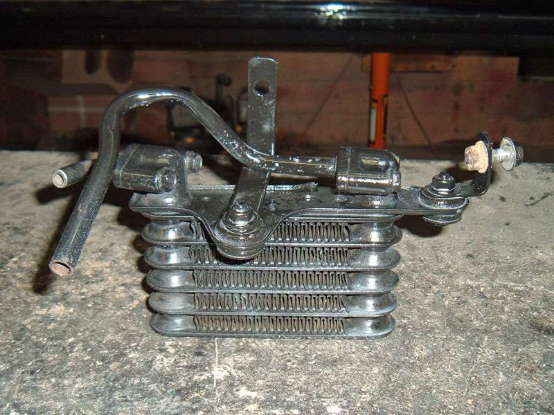
I built the unit using stock gears bearings, and cluster but did upgrade the bearing retainer on the front of the transmission to a solid one piece steel unit. 

I also upgraded the counter gear stabilizer in the transmissions.  


As you can see from the pictures solid counter gear stabilizer is a much stronger part than the original stamped steel retainer.  The biggest advantage to a solid piece like this is that unlike the stamped piece a solid retainer will not stretch during use. This insures that the counter gear cluster is always correct orientated and never floating in the case, which strengthens the over all torque and horse power ratings of the transmission.  Once I had my transmission together I was ready for it to go in the car.

Changing the Engine?
There was a time when there was a major drawback to upgrading to a T5 transmission especially for cars like the Galaxie, and that was that a T5 would not bolt directly to anything except the 6-bolt Windsor series small blocks.  In the case of a Galaxie this is a major issue as those prior to 65 did not come from the factory with a 6-bolt small block Windsor and the majority of these cars came with the FE series engines.  
In the case of an FE, not only was the transmission bolt pattern different, but also the input shaft on a T5 is much longer than the input shaft on the original manual transmissions found in these cars. The Input shaft length differences, between a T5 and an FE type 3-speed or 4-speed, could be over come by using a FE truck bellhousing and a T5 adapter plate between the T5 and the bellhousing, but I prefer a one-piece bellhousing to this type of system.  A much better option comes from a  company called quicktime that now makes a bellhousing designed to bolt a T5 directly to an FE series motor.
For my 1962 Galaxie T5 install, upgrading to a T5 bellhousing was as simple as finding a 5.0 T5 bellhousing and bolting it up.  This was due to the fact that when I first got my Galaxie mobile,  I did so by removing the FE series 352 and installing a 302 from a donor 84 mercury grand marquise. Using the OEM T specific bellhousing not only made the install easier but also allowed me the opportunity to upgrade to the smoother action of a hydraulic clutch, and I had the added benefit of being able to use an OEM type mini starter used in 1993 Mustangs.  An OEM starter is far less expensive than the aftermarket mini starters available, is much smaller than a typical Ford starter and cranks the engine faster with less draw on the battery.

Flywheel Weight
When installing a T5 it is important to make sure you have the correct flywheel balance regardless of the motor that you are bolting the flywheel to.  Obviously you want to use the correct balance for your application.  Also when using a T5 specific bellhousing you need to make sure your flywheel will except a diaphragm clutch.  In many cases theses more modern diaphram type clutches have metric bolt patterns, which require a matching flywheel.  With that in mind balance is even more important if installing a modern 302 flywheel on an older Windsor series small block.  
Ford balanced their Windsor series engines two different ways.  All 221, 260, 289, and 351 engines were balanced at 28 ounces.  The issue comes with the 302.  All 302 engines made prior to 1982 have a 28-ounce balance, but all engines made from 1983 up are balanced at 50 ounces.  As is typical of Ford in the transition year of 1982 you have some of both.  You must make sure you have the correct flywheel balance for your application because if you put the wrong flywheel balance weight on an engine it will shake like it is trying to come apart. 
 This is especially important to keep in mind because the flywheels fond in front of most T5s in an OEM application are going to be of the 50 ounce weight and that means if retrofitting your T5 to an older Windsor series engine an aftermarket 28 ounce T5 flywheel will need to be purchased, or the original 50 ounce flywheel will need to be rebalanced by a machine shop.
Install
The over all install of a T5 in to a 62 Galaxie is really no different than any other manual transmission in any other car, however, there are several tips and tricks that I have learned that you can use to make sure the install goes as easily as possible. 
Grease as a Bearing Removal Tool
The first thing that needs to be installed in the car is a new pilot bearing.  Even if the car was a manual transmission before it is still a good idea to get a new roller stile pilot bearing designed for the 85-93 Mustang with a 5.0.  To get the old bearing out simply use a grease gun and a 5/8” piece of round stock.  What you do is squirt grease in to the cavity behind the bearing and then place the round stock into the bearing opening and tap the rod with a hammer. 
 Just like hydraulic fluid the grease will not compress and as you force the grease into the cavity behind the pilot bearing it will push the bearing out.  It will probably take several liberal applications of grease and several taps of the hammer on to the rod to get the bearing out.  Once it is out clean the opening with a rag and install the new bearing.
From there the normal parts that need to be installed can be: block plate, flywheel, clutch, and clutch pressure plate.  When torquing down flywheel bolts I use a steel rod between the floor and one of the side teeth on the flywheel to keep the flywheel from turning as you as the bolts are torqued.  When installing the clutch make sure to use a clutch alignment tool as you tightening down the pressure plate.  This will position clutch close to the correct alignment which in turn will make the install of the transmission much easier.  

With all the internals of the bellhousing installed the bellhousing can go on. Don’t forget to install a new throughout bearing on the clutch fork.  With the bellhousing installed it is a good idea to turn the engine by hand to insure that there are no clearance issues between the pressure plate and bellhousing.  Once you know everything clears, you are almost ready to put the transmission in, however there are a few more tips that will make putting the transmission in a little easier. 
Take the Shifter Off
Due to the fact that the shifter bolts to the top of the T5 tail shaft housing, it may seam like a good idea to try and install the transmission with the shifter already installed on the transmission, but unfortunately this is not the case.  Attempting to install a T5 with the shifter on will drastically reduce the clearance between the top of transmission and the transmission tunnel as you install the transmission which reduced clearance making it much harder to line up the input shaft with all the parts in the bellhousing.  Prior to removing the shifter, make sure the transmission is in gear.  The reason for doing this is so rotating the output shaft will turn the input shaft and  allow you to line the input shaft splines up with the clutch splines. 
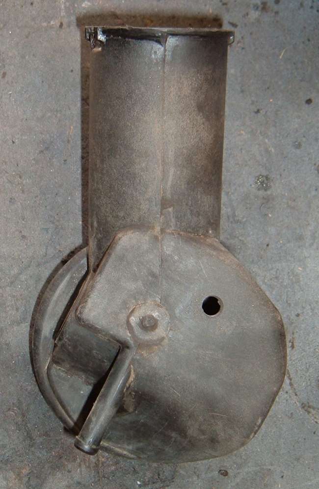
Plug The Holes
When installing the transmission it is important that dirt and other contaminants do not get in the transmission and fluids do not get out.  There are three main holes  that need to be plugged.  Start with the shifter opening.  This needs to be covered with tape so that dirt from the underside of the car does not fall in to the opening.  

If installing the T5 dry, plugging the next two holes is not as critical but if the transmission has fluid in it than it is a must, to avoid spilling fluid all over yourself and or the floor.  The two holes I speak of are the tail shaft opening and the speedometer gear opening.  To plug the tail shaft opening simply slid a slip yoke in to the back of the transmission and secure it with string, wire, or a couple of zip ties.  

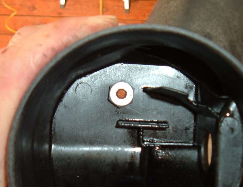
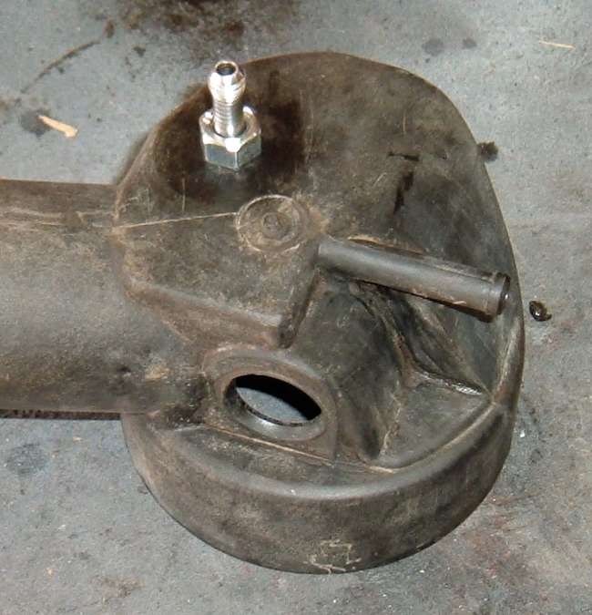
To plug the speedometer hole I took the end off of a bad speedometer cable, removed the cable and plugged the hole in the middle with some oil resistant silicone.  

This provides me with the perfect plug for the speedometer gear hole. 
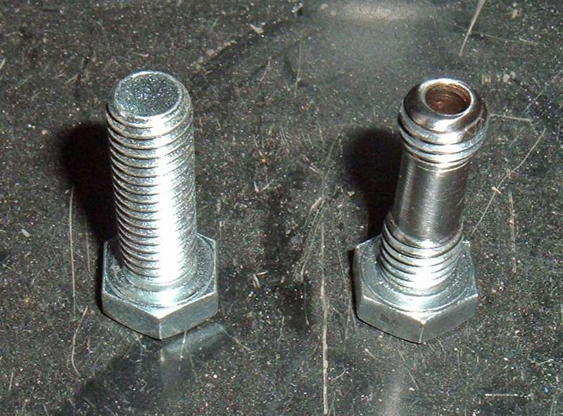
Guide Studs
Guide studs are one of the simplest things you can make and yet one of the most effective in making the actual install of many different parts easier.  I have a whole collection of guide studs that I have made for all sorts of applications such as installing an intake manifold, lining up a flywheel on the crank and for this project, installing a T5 transmission.  All you need to make a guide stud is a bolt that is about 1” longer than the OEM bolt for its intended location and a way to cut off and round the head.  Once you have them made you simply screw them in place and in theory slide the part over them.

When using guide studs the only thing you need to remember is after the part has been installed, only remove one stud at a time and replace it with the actual fastening bolt prior to removing another guide stud.
Jack Plate
For those that do not have the benefit of a transmission specific jack, on some transmissions like the toploader there is a natural place on the bottom of the transmission where you can put a regular floor jack to help get the transmission up in the air .  This is not the case on a T5.  All of the places where you can stick a jack do not provide a solid enough mounting point or a good balancing point.  This makes the transmission extremely unstable as you jack it up, which in turn makes lining everything up even harder.  By making a jack plate out of a flat piece of steel and some all-thread or a few bolts you create an adjustable platform that provides a flat place for the jack to rest and a stable cradle for the T5 to sit in.  


Stab the Transmission in
This can be the single hardest part of a T5 install.  The input shaft has to pas through the  bellhousing opening, into the throughout bearing, through the clutch and then in to the pilot bearing.  Not only does the transmission have to be at the correct angle so that the input shaft is perpendicular to all these parts, but all the parts in the bellhousing must be perfectly lined up.  Chances are this is not going to be the case as the throw out bearing and clutch fork have a lot of play in them and the clutch will probably be slightly off even if a clutch alignment tool was used.  
The first thing to deal with is the throughout bearing.  This can be done by either having some one else hold the clutch fork stationary or by tying or taping it in place.  This will allow you to get the input shaft  in to the bellhousing and through the throughout bearing.  Once the transmission is installed far enough that the input shaft is through the throughout bearing you should be able to get the transmission mounting holes on to the guide studs.  
As you slide the transmission further in it will probably bind up as the input shaft splines catch on the clutch splines and you will need to turn the output shaft to get the input shaft to line up with the clutch.  Once the splines are lined up the input shaft should slide through the clutch as you to push the T5 in a little further, but chances are it will get stuck again with the front of the T5 case about 3/4" away from the bellhousing.  

This issue is caused by the clutch not being perfectly lined up with the pilot bearing.  The clutch being slightly off will pull the input shaft out of alignment with the pilot bearing hole causing the tip of the input shaft tip to bind against the pilot bearing. 
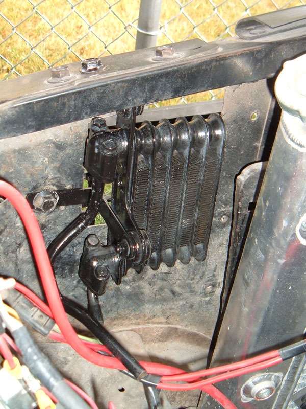
Clutch Engagement Tool
A very common mistake made during this part of a transmission install is to use the mounting bolts to close the 3/4" gap.  If you install the mounting bolts and then tighten them down the transmission may slide in to place however you run the risk of damaging the clutch, input shaft and or pilot bearing as well as potentially cracking or breaking off the transmission mounting tabs.  
A much better solution is to disengage the pressure plate from the clutch allowing the clutch to slide in place.  On a T5 this can be done by placing a long bolt or piece of all thread through the clutch fork and the OEM cable mounting tab on the bellhousing and then tightening the nuts down until the clutch can move freely.  

Once the clutch is loose the transmission should slide right in.  From there you can bolt it in place and then move on to the transmission crossmember.
Building a Crossmember
In many cars like my 62 Galaxie the transmission crossmember had to serve a dual purpose.  It not only holds the transmission in place, but also ties the two frame rails together.  This means that it is a structural component of the car and weather you choose to fabricate a new one or modify the original transmission crossmember you must keep strength in mind.  
Like I said in the beginning of this article, this install, unlike a Mustang T5 install, does not have the benefit  of aftermarket support. Since I could not buy a crossmember, I chose to build one from scratch using 3/4” square tubing.  

The easiest way to build a crossmember from scratch is to do it in three separate pieces.  Build the flat piece that goes across the bottom of the transmission mount, then build the two pieces that attach to the frame.  The three pieces then need to be bolted into the car, and the transmission needs to be correctly centered in the transmission tunnel.  From there you can tie the tree pieces together by tack welding some scrap steel between the center piece under the transmission and the two pieces at the frame. 
 With the three pieces tacked together the full assembly can be removed from the car and new pieces can be cut and welded in to place so that the scrap steel can be removed.  Make sure the new pieces are only tack welded and that you test fit the crossmember one more time before you burn it in permanently.  Once you have it built you can paint or powder coat and then install it.
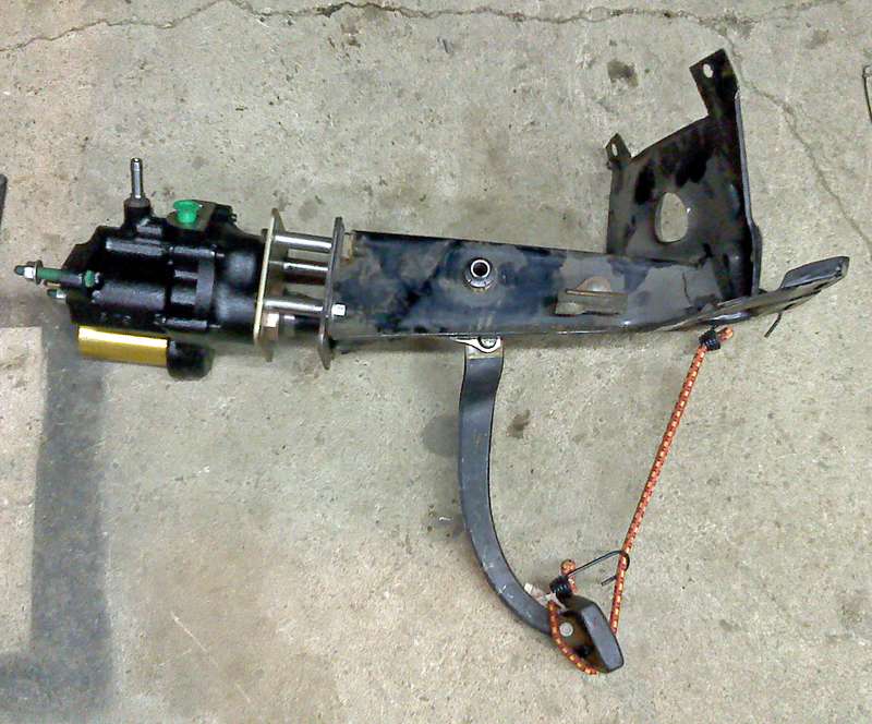
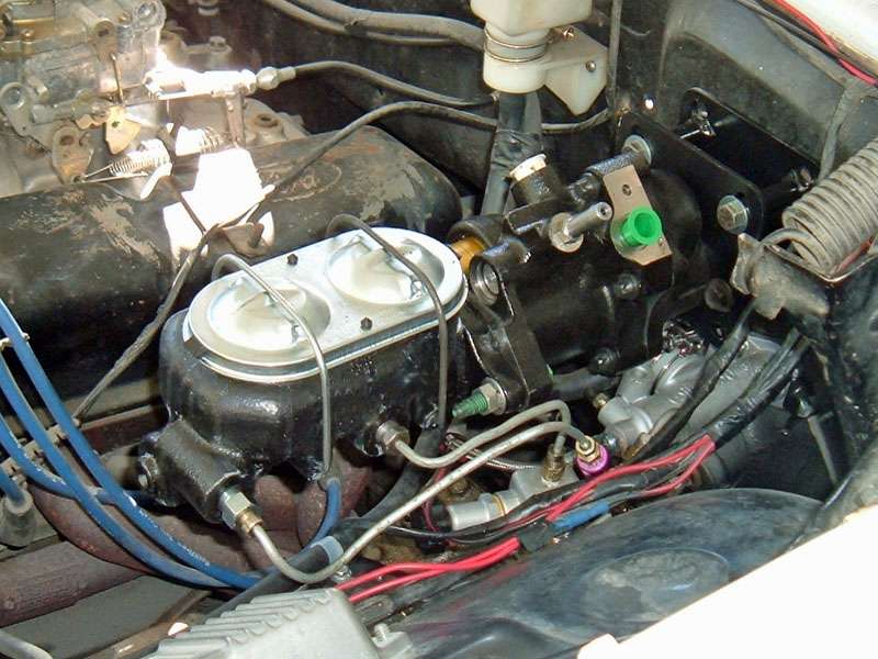
Getting the Rest of it Hooked Up
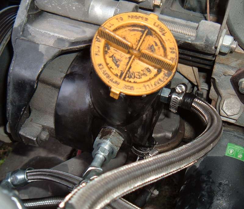
The rest of the install is just the basics, hook up the clutch linkage, (in my case hydraulic)  http://www.fordmuscleforums.comtransmission-articles/481776-hydraulic-clutch-classic-ford.html pull the plug and install the speedometer cable, then install the drive line.
  
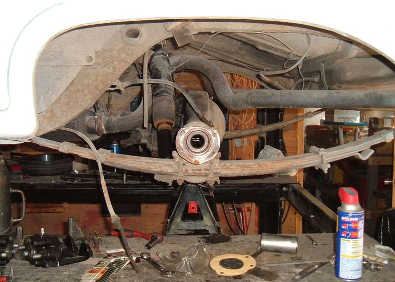
Slip Yokes and Drive Lines
It is important to have the correct slip yoke for a T5, but the good news is you may be able to use the one you already had with a little modification.  T5 and AOD transmissions both use the same slip yoke.  The C4 and Toploader also use a slip yoke that can be made to work.  The slip yoke on the C4 and toploader has the correct splines but is to long.  

All you need to do is cut off the unsplined section of the yoke and you will have  converted your C4 or toploader slip yoke in to a T5 slip yoke.

In most cases installing a T5 in your classic will require you to have some drive shaft work done, when taking your measurements make sure you have .75” to 1.5” clearance between the end of the transmission and the shoulder of the slip yoke.   

On the T5 install in my Mustang the drive shaft was about .5” to long prior to having drive line work done, but on the Galaxie T5 install the drive shaft was about 7” to short.  Take your drive shaft to a shop with a good reputation, and even if it costs extra, make sure you have it balanced.
Adding Fluid
The easiest way to add fluid to a T5 is trough the shifter opening.  There is a drain hole in the shifter opening that drains in to the tail shaft housing and from there in to the main case.  To fill the oil, with the car level,  remove the fill plug and begin poring oil in to the shifter opening until the oil comes out the fill plug opening. 
 Keep in mind that it may take a few minutes for the fluid to drain in to the main case so to avoid a mess add the fluid a little bit at a time especially after the first two quarts have been added.  

As I said before world class T5 transmissions use ATF as a lubricating oil, but there are also companies out there like royal purple that make a fully synthetic manual transmission fluid specifically for manual transmissions that use ATF.  The advantage of a fluid like this is that it is specially formulated to prolong the life of synchronizers. 
Final Thought
Over all this was one of the best upgrades I have made to the old Gal.  That car has a lot of weight and that 302 needed all the help it could get to move that weight.  By installing the T5 I am in control of the shift so I can maximize power and the lower first gear ratio gave me more off the line power.  Don’t forget the added benefit of that 5th gear.  Galaxies are wonderful cars to cruise in and being able to drop the RPMS down at highway speeds only adds to the cursing enjoyment.

Daze wrote:

One extremely popular “junkyard” upgrade for classic cars is to install a 5-speed from a 1985-1993 Mustang.  Regardless of the year or model of car that the T5 is going in, one major hurdle is to figure out how to actuate the clutch. There are several options, due to the fact that the T5s  installed by Ford as OEM equipment used a T5 specific bellhousing, and the clutch fork on that bellhousing is actuated by moving it toward the front of the car where a toploader or T10 bellhousing that might have been OEM on a classic is actuated by moving the clutch fork towards the rear of the car. 

 These options include using the stock clutch z-bar/linkage with stock bell housing and T5 specific adaptor plate between the transmission and bellhousing, a T5 bellhousing that has been modified to except a traditional type clutch fork so that it will work with stock clutch z-bar/linkage, a T5 bellhousing with the clutch fork actuated by a cable as ford originally did it on the 1985-1993 Mustang, or the T5 bellhousing with the clutch fork actuated by hydraulics.

I have installed a T5 in both my 1964.5 Mustang and my 1962 Galaxie, and in both cases I chose to use hydraulics. For me, part of the advantage of going with a T5 was to eliminate the original z-bar/linkage.  That only left me the options of a cable or hydraulics.  Cables can work well, but they can also stretch and/or break requiring adjustments or replacements.
 
Hydraulics on the other hand have proven them selves exceptionally reliable and nearly maintenance free once correctly set up. Lets face it every car on the road, new or old uses hydraulics to actuate the brakes, which means the method, is sound. 
 
Master cylinder
Just like the brakes, you need to have a master cylinder to push the fluid.  In the case of a hydraulic clutch room is often a premium due to location of the brake master cylinder and other things attached to the firewall so it is recommended that you get a master cylinder that has a remote reservoir that way you can mount the master cylinder in the proper location on the firewall to easily connect it to the clutch pedal but locate the fluid reservoir where you have room for it. I like the Wilwood universal master cylinder available at many part suppliers and speed shops including speedway motors.  It not only has the remote fluid reservoir but also comes in a verity of bore sizes so that it can be correctly sized to the slave cylinder.


Slave cylinder
The slave cylinder is a key components as it is what converts the hydraulic pressure back in to mechanical motion to actuate the clutch.  There are many donor cars out that that use a slave cylinder so junk yard parts are available, but I prefer new parts.  To the best of my knowledge there is only one aftermarket push type Slave cylinder available even though it is sold under several manufacturing names, and like the Master cylinder can be purchased at many places including speedway motors.


Master cylinder to slave cylinder ratio
When purchasing your master cylinder and slave cylinder you must look at bore size and piston travel. For best results you want the master cylinder to have at least 1.25” of piston travel and a bore size that is either equal or slightly smaller than the bore of the slave cylinder, keeping in mind that most slave cylinder bores are .75” or .825”.  

The way hydraulics work, if you use a master cylinder and slave cylinder with equal bores than the pressure required to actuate the master cylinder will be approximately the same pressure applied by the slave cylinder, in other words the pressure required to actuate the clutch by the slave cylinder will be almost equal to the pressure needed to actuate the master cylinder at the pedal (I say “approximately” and “almost” because resistance is created by hydraulic lines which results a slight difference in pressures between the master cylinder and slave cylinder, but this difference is really not to be worried about for the sake of this installation). 
 
In contrast if the master cylinder has a smaller bore than that of the slave cylinder, less pressure is required to actuate  the master cylinder than the  pressure created at the slave cylinder to actuate the clutch.  The reduction in pedal effort comes at a cost of reduced slave cylinder travel.  Example if the slave cylinder and the master cylinder have the same bore, 1.25” of piston travel at the master cylinder will result in 1.25” of travel of the piston in the slave cylinder, but with a .75” master cylinder and .825” slave cylinder the difference in bore size will result in about a 17% reduction in pedal effort and the 1.25” of master cylinder travel becomes 1.04” of slave cylinder travel.

Hydraulic lines
Some sort of line needs to be used to connect the master cylinder to the slave cylinder.  As with the breaking system there are three man options: rubber hydraulic hose, braded steel line, and hard steel line.  No mater which option you choose to go with make sure there is flex in the line at some point other wise the vibrations from the transmission could cause solid lines to fail.

Slave cylinder pushrod
Some sort of rod needs to be used to connect the slave cylinder to the clutch fork.  There are rods commercially available that firmly attach directly to the clutch fork, however I do not like these, as they do not allow the joint between the pushrod and clutch fork to pivot as the clutch is actuated.  For me a better option is a piece of [url="http://dazed.home.bresnan.net/test#2"]threaded rod and a spherical piece of steel[/url]. 


Mounting bracket
The makers of the T5 were kind enough to supply tabs for mounting a slave cylinder, however the tabs will not bolt directly to the slave cylinder.  This means a bracket needs to be fabricated or [url="http://home.bresnan.net/%7Edazed/test#3"]purchased pre-made[/url] to properly position the slave cylinder and connect it to the transmission. 


Firewall support
It is important to realize that for most applications the area of the firewall where the clutch linkage originally passed through is not strong enough to deal with the pressure of actuating the master cylinder and bolting the master cylinder directly to the firewall with out any kind of reinforcing plate would at the least flex and deform the fire wall but more likely could cause the master cylinder to brake loose from the firewall during use. An easy fix for this is a thick steel plate on the inside of the firewall to more effectively distribute the pressure of the master cylinder against the firewall.

Bolting on the slave cylinder and master cylinder
Attaching the slave cylinder and master cylinder to the car in their respective locations is simple.  Bolt the slave cylinder bracket to the transmission mounting tabs then bolt the slave cylinder to the bracket. 


From there you can install the push rod between the slave cylinder and clutch fork. 
Once the rod is installed you need to make adjustments so that there is a little bit of preload on the throwout bearing.  Also further adjustments may need to be made depending on where in clutch pedal travel you like the clutch to release. I personally prefer it to release closer to the floor rather than near the top of pedal travel.  Finally the hydraulic lines need to be attached to the slave cylinder.  

The master cylinder bolts in, in the same fashion, with the exception of needing to drill mounting holes in the firewall and possible needing to enlarge the original clutch linkage hole.  As with the slave cylinder the hydraulic lines need to be attached to the master cylinder.  Also if using a master cylinder with remote reservoir, the reservoir will need to be mounted and connected to the master cylinder.


Bleeding the system
Once everything is bolted up and the lines have been run the system like brakes needs to have all air removed. This is a two-man job and is critical. Most of the time when people are having problems setting up their hydraulic clutch it is because they have not gotten all the air out. Sense air, unlike hydraulic fluid, compresses, air in the system will reduce slave cylinder travel and causes the clutch fork to not fully actuate. Also as the system the bled you need to examine all connections between the master cylinder and slave cylinder to insure there are no leaks. Bing a pressurized system leaks should be obvious as the air is removed.

Connecting the master cylinder to the pedal
One thing that is critical when doing a hydraulic clutch install is to make sure the master cylinder push rod mounts to the pedal in a place that keeps said pushrod mostly parallel with the master cylinder through a full range of motion. I say mostly parallel due to the fact that as the arc of the pedal changes, rod angle also changes and I have found for best results the rod needs to be angled slightly up from parallel with the pedal in the fully up position, so that it can drop as the pedal is pressed. On my mustang the original clutch hole is only about 1” lower than the mounting hole that I drilled in to the clutch pedal to keep things parallel, but on my 62 Galaxie the hole for the clutch linkage is about 2.5" lower than the pedal-mounting hole. The location of the firewall holes and the need to have the pushrod near parallel to the Master cylinder gave me quite a problem to solve especially on the Galaxie. I couldn't easily relocate the clutch linkage hole and tilting the Master Cylinder down to match the original linkage angle would have required the fabrication of a special bracket. The first option to make it work was to drill a new hole in the clutch pedal and move the pushrod mounting point in-line with the master cylinder. This worked on the Mustang sense the relocation was only about 1” and resulted in only slightly increased pedal effort and decreased pedal travel. Many who have installed a hydraulic set up on a classic mustang have used this technique.

However the 2.5” drop on the Galaxie did not make this an option, and I learned that the hard way. When I drilled the new hole I new that the 2.5" drop from the factory location would increase pedal effort and shorten pedal travel but I figured sense most say their hydraulic clutch requires less pedal effort than stock I would be fine. WRONG!!!! took a lot of pedal effort and the master cyl bottomed out 2" before the pedal reached the floor. I thought OK I will use the higher mount as a pivot and run a 5/8" block perpendicular to the push rod from the pedal to said pushrod to connect it to the original clutch linkage hole. This allowed me to maintain the correct pedal geometry and master cylinder location.

This set up immediately bent the 5/16" pushrod that came with the MC so I machined one out of a 3/8" grade 8 bolt (Man I love have a metal lathe!!!!!!!!!). Bent that one too but not as bad, and I was able to at least actuate the clutch and make sure it worked and that pedal effort was reasonable. The final solution was to triangulate the push rod by threading most of the push rods length and making an adjustable connection to stabilize the rod. 


This solution could also be used on the Mustang to reduce pedal effort and maintain the original pedal geometry, not to mention avoid drilling a second hole in the pedal and would probably not require the extra triangulated support. 


Over all I am very pleased with the result, the clutch is easy to actuate and very smooth. Also the hydraulics provide an improved direct feel over what I got with the original linkage.  In other words I can feel the change in pedal effort just as the clutch releases or grabs, but the feel is crisper than before as there is no longer the flex I was getting from the z-bar and other clutch linkage.

69crewcab wrote:

and three the rear disc swap, i see you went with mark vii parts and the after market brackets
Ever try using the explorer or crown vic brakes on your 9"

I have not used the the other options, but I know there are lots of good ones out there.


March 22, 2013 8:28 pm  #5


Re: hydroboost possible?

Daze

AWESOME Article!!!
one question, being that im a big fan of junyard hunting, what vehicles could i pull the
hydraulic clutch from? I even saw on rock auto an earlies 90's bronco
has a hydraulic setup as does my 91 escort gt
just wondering for my spring upullit trips 


64 Galaxie Country Sedan Wagon
69 XL Convertible "390" w/ Air
1990 Crown Vic Wagon
     Thread Starter
 

March 23, 2013 1:34 pm  #6


Re: hydroboost possible?

I would not use junk yard hydraulic parts.  It is kind of like brakes, most people use new or reman master cylinders and wheel cylinders rather then Junk yard parts.  If you want to use OEM parts I am sure you could find some at the auto parts store for a good price.  I am all for recycling used parts, but not hydraulic.  IMHO


March 23, 2013 3:15 pm  #7


Re: hydroboost possible?

Daze
I should have said
Would like to find a junkyard setup
As a trial and fit unit
And then just replace it
I see some 80s ford trucks
With a hyd setup that might work


64 Galaxie Country Sedan Wagon
69 XL Convertible "390" w/ Air
1990 Crown Vic Wagon
     Thread Starter
 

March 23, 2013 4:13 pm  #8


Re: hydroboost possible?

69crewcab wrote:

Daze
I should have said
Would like to find a junkyard setup
As a trial and fit unit
And then just replace it
I see some 80s ford trucks
With a hyd setup that might work

You realize I sell a kit for hydraulic clutches??  I could even make a MC lowered pushrods for you but it would be a different design than what I did. Ther is a much cleaner way to do the same thing. 


March 24, 2013 7:39 am  #9


Re: hydroboost possible?

Nope didnt know that how much
And whats all in it?


64 Galaxie Country Sedan Wagon
69 XL Convertible "390" w/ Air
1990 Crown Vic Wagon
     Thread Starter
 

March 24, 2013 8:39 am  #10


Re: hydroboost possible?

Take a look at these.  none are Galaxie specific but will give you an idea of what I offer

http://dazed.home.bresnan.net/test#3


Board footera


Powered by Boardhost. Create a Free Forum