It is an interesting story how I came across this conversion. While surfing the net on Galaxies, I came across an article about an owner converting to rack and pinion steering on a custom restoration. When the article mentioned absolutely no bump steer, I was sold. Thru further research I discovered a company (that no longer exists) that did manufacture "BOLT ON" kits which also captured my interest because of my limited skills. The kits were selling for $1700.00 dollars when they were available in about 2005-2007. They seemed pretty simple in design and fabrication, a few brackets and a rack. A while later, I located an Article in a Custom Rodder magazine where they did an actual install with the said kit. Contained in the article were some pictures and simple install explanations. Finally, while at Barrett Jackson auto auction in Las Vegas last year, I came across a Galaxie with the kit installed. I spoke with the owner who confirmed no bump steer and the car had good steering. So after a couple of years of gathering information and with the pictures in the magazine article, I decided to give it a try.
Now to anwer your questions: No I didn't do anything to change the lock to lock, I wouldn't know how. There have been a few articles in some forums stating your turning radius is not as tight with this set up. The output shaft goes straight up because of the way the kit brackets are fabricated and installed and because of the design of the rack.
The rack is a GM center steer unit, I harvested it off of a 90's Cavalier for $40.00. To hook up the steering column to the rack out put shaft, a Borgeson double u joint is used at the rack with a 3/4 inch double DD shaft and a single u joint used at the steering column. The double DD shaft is supported by a rod end bolt which is adjustable. I purchased all of these parts thru Jeggs, cost about $315.00
I wasn't able to find anyone who used this kit in combination with a hydroboost, so as far as I know, I may be the first to try it. The stock steering column is retained on the car. The challenge I have right now is to figure out how to make the connection of the new steering components to the flange on the end of the steering column where the rag joint used to be, as I could not find any pictures showing this. I have a few ideas, but not sure. No rag joints are retained with this conversion.
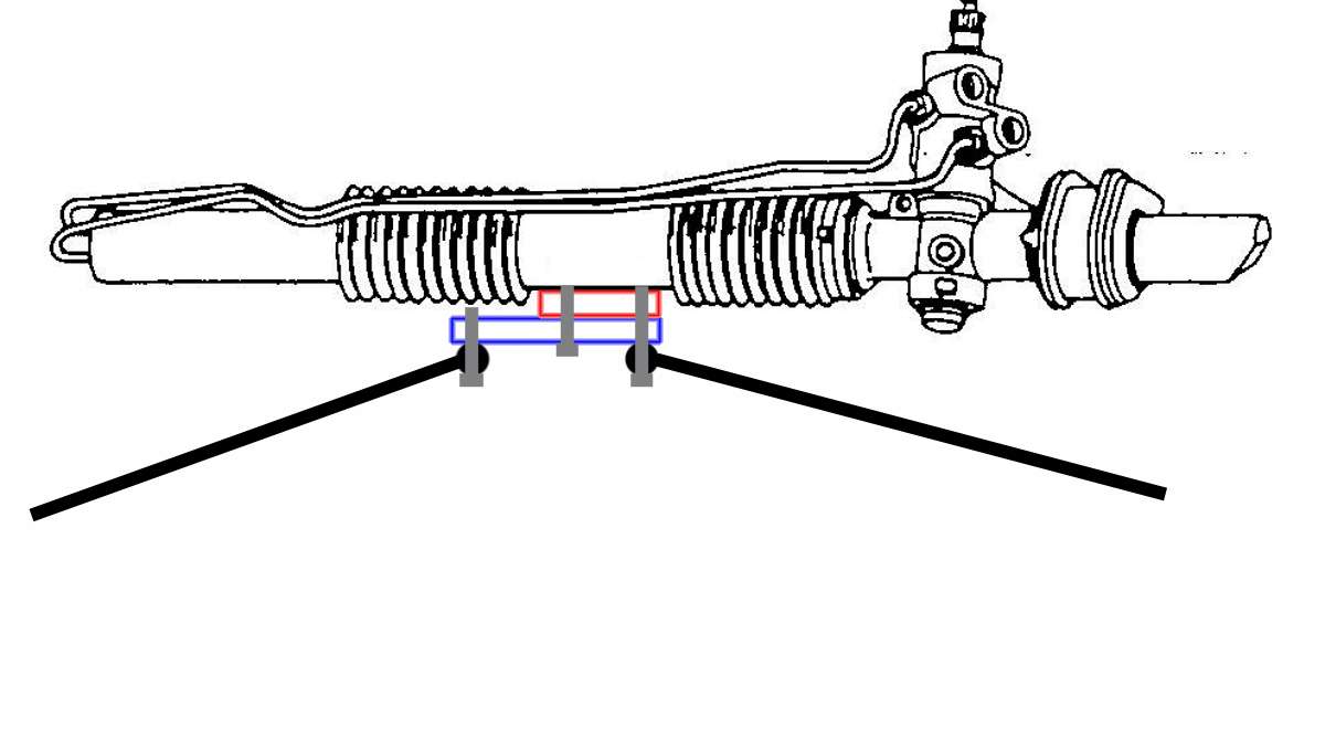
One slight difference I did discover is the inner tie rods will be located in the same location as original, however, they are slightly closer together. This will mean I have to change the grease nipples to a 90 degree style. The center link tie rod holes are 4 5/8 inches center to center, the offset bracket connecting the rack to the tie rods will reduce this by about an inch less, strictly for clearance. I can't see this affecting the steering geometry that much, but I am no expert on this subject, just a guess.
Again, I am fabricating this system, strictly off of pictures. The brackets may not be to exact dimensions as available in the kit, but should be pretty close.
One last thing. I am installing a 4.6 with overdrive. The 4.6 came out of a Crown Vic and on those engines a rear sump oil pan is used. To clear the cross member, a front sump oil pan is required. Luckily, on the front wheel drive Lincoln's from the early 90's, they used front sump pans. At a local salvage I was able to grab a front sump oil pan, oil pick up tube and dip stick for $100.00.
Hope all this helps. Need any more info, let me know, I will try to help.

 1
1 
 dan_6776 wrote: