Galaxie Forum Full-size Ford, Lincoln, and Mercury DazeCars www.galaxieforum.com


This forum is for all years of the Ford Galaxie and all other Full-size Ford, Lincoln, and Mercury cars. This is a place to share information, skills, pictures, and stories for the purpose of building friendships and furthering the enjoyment and restoration of these cars

You are not logged in. Would you like to login or register?


March 1, 2017 4:33 pm  #1


dan_6776, I have started (steering arm shortening)

I am working on modifying my steering arms to correct the reduced turning radios of our R&P setup.  I know it was a long time ago when I first mentioned this , and I also know you have asked about it many times, but until now I had no updates.

Every time I worked on it I never was able to resolve a few issues I was having, the biggest being the best way to mount a new arm to the spindle and still have the shape right and in the correct orientation so that the flat of the tie-rod mount was perpendicular to the machined mounting face. In the long run the arm will be cut from angle iron but as I design it I will probably make it out of wood. (more to come)  I think I have figured it out and  have started the process today of building a fixture that will locate the OEM mounting location and orientation.  I need this so I can completely cut off the original arms to get them out of my way as I design the new arm.    Best part is  I think I have a fixture design that can be used for both sides by making it two piece and bolting the two pieces together I can remove the pieces reverse them and bolt them back together.  More to come as the project develops.


March 1, 2017 8:44 pm  #2


Re: dan_6776, I have started (steering arm shortening)

Excellent!
Post some progress pics if you can.


March 4, 2017 10:23 am  #3


Re: dan_6776, I have started (steering arm shortening)

I have been thinking more about this project you are working on.
Just a guess here...is the main objective to lengthen the OEM spindle tie rod mounting arm? That way the longer spindle arm compensates for the decreased travel of the rack? By so doing you regain your full turning radius?
If so, why couldn't you simply cut the spindle arms add what you need, weld and add reinforcing for strength and be done?
I'm sure it's not as simple as that, but I would be curious to know why my thinking wouldn't work. Is the spindle a cast piece and welding it creates weakness?
Just curious😉


March 4, 2017 11:57 am  #4


Re: dan_6776, I have started (steering arm shortening)

dan_6776 wrote:

I have been thinking more about this project you are working on.

well thats the first problem I try to think as little as possible... to painful 

dan_6776 wrote:

Just a guess here...is the main objective to lengthen the OEM spindle tie rod mounting arm? That way the longer spindle arm compensates for the decreased travel of the rack? By so doing you regain your full turning radius?

Your thinking is almost correct, but backwards in one key area.  By lengthening the steering arm you reduce turning radius for a specific amount of steering travel.  In our case we need to increase the turning radios so the answer is the reverse, we need to shorten the arm.

dan_6776 wrote:

If so, why couldn't you simply cut the spindle arms add what you need, weld and add reinforcing for strength and be done?
I'm sure it's not as simple as that, but I would be curious to know why my thinking wouldn't work. Is the spindle a cast piece and welding it creates weakness?
Just curious😉

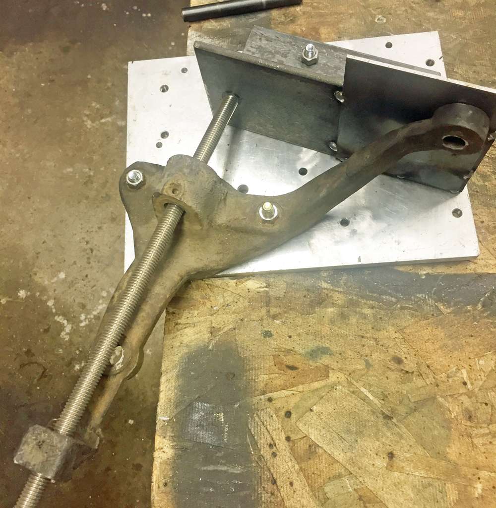
So again you are 1/2 way there.  I am cutting off the old arm but the piece is also cast steel so welding is not a good option.  Assuming I can make this work, I will do what GM has done for years and make the arm a bolt on.  Here is my process so far.

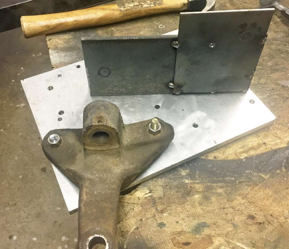
The first thing I did was build a fixture to hold the spindle and locate the two important points, the spindle pivot point, the OEM tie rod location.   

You need these points to insure the correct Ackerman angle.  Ackerman is what allows the inside tire (when turning) to turn more sharply than the outside tire.  Ideal Ackerman (not all cars use ideal Ackerman) is calculated by drawing a line from the spindle pivot to the center of the rear axle.  


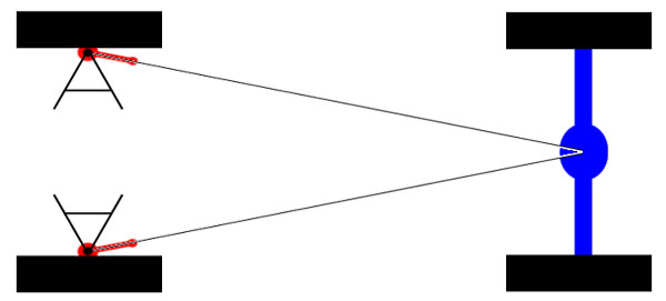
As long as the tie rod mount is some where along that line than Ackerman will be correct.  The closer it is to the spindle pivot the quicker the arm will turn and the further away the slower.  In our case we have less steering travel so when need it to turn quicker.  I used a piece of string and confirmed that the Ackerman angle on our cars is ideal.

Once I had the two points I took the jig apart and located where the new tie-rod location should be.  I used photoshop to mark the picture.  White is the Ackerman line, black is the spindle pivot, red is the OEM tie rod location and blue is 1.5" in from the red and is the new location.  Moving it in that far should give me the extra travel I need.


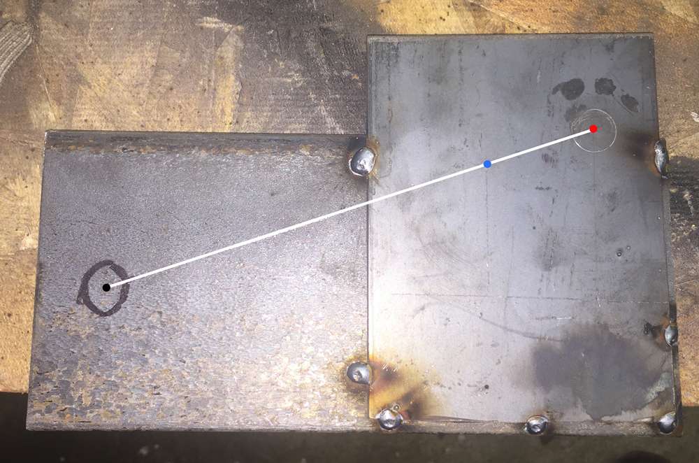
After I got it all mocked up I drilled a 1/4" hole in the new tie-rod location on my fixture so that I can use a transfer punch to correctly locate the new hole as I design the replacement arm.

Once I had my fixture done I put a 4.5" cutoff when in my angle grinder and cut the steering arm off.  I am really glad this is an extra set of spindles so that if I fail I am only out a spare part.


Thats all the further I got yesterday.  I will now build the arm on the fixture and spindle (probably out of wood first) so that I can get the correct shape and pattern before making it out of steel.

     Thread Starter
 

March 4, 2017 9:39 pm  #5


Re: dan_6776, I have started (steering arm shortening)

Amazing stuff Daze! 
That's why I ask so many questions...I think I understand...but sometimes I don't!
Seeing those pics really helps me to understand. Great work so far...looking forward to the next update!
Do you have any pics of those GM spindles you mentioned that are bolted together or an example of which cars had them? I would like to look into this.
Oh yeah...another question...how did you determine that removing 1.5" of tie rod arm would be what you need to get the turning radius back to where it should be?

Last edited by dan_6776 (March 5, 2017 7:19 am)


March 5, 2017 3:05 pm  #6


Re: dan_6776, I have started (steering arm shortening)

Here is the picture of a Chevy II spindle with removable arm and below it is a Chevy bolt on arm but I'm not sure what car it is designed to fit on.


[img]http://i.ebayimg.com/00/s/ODcwWDEyMDA=/z/DeYAAOxyA4ZRLU5v/$T2eC16FHJGYE9nooiLRzBRLU5vZgMw~~60_35.JPG[/img]

Below is another bolt on set up that inspired me to make mine out of angle iron however mine will be totally different as the steering arm on our cars hangs way below the lower ball joint mount.  Also the arm on the right is made of 3/8" steel so I have a baseline as to what I need my thicknesses to be as I use my back yard engineering philosophy  "Make a good educated guess as to what will be strong enough based on whats available in the aftermarket and then reinforces and increase its strength to be more than strong enough."


As far as my calculations to determine that removing 1.5" will be just right, I used "close enough math"  converting lateral movement into an arc is a far more complicated calculation than I felt like doing, but I knew I could get close enough using ratios.  The OEM arm from ball joint hole to tie rod hole, is 7" the OEM steering travel was 6.75" and the rack travel is 5.625"

5.625/6.75 = .83 the ratio between the rack and OEM steering

.83 * 7 =  5.81  My ratio * to OEM steering arm

So by creating a ratio of the Rack travel to the OEM travel and then multiplying that ratio by the OEM steering arm length I get a new length of 5.81.  I would rather have to much travel and need to limit it with some sort of stop than not have enough travel so I rounded down to 5.5" as the new length for my steering arm.

     Thread Starter
 

March 6, 2017 9:26 am  #7


Re: dan_6776, I have started (steering arm shortening)

This is looking real cool. Keep us updated as things progress, please.


March 6, 2017 11:23 am  #8


Re: dan_6776, I have started (steering arm shortening)

It has been one of the harder projects I have done so far because there is so much in that area of the suspension trying to take up the same space.  The OEM arm doesn't even follow the Ackerman line (even though the final tie-rod location is correct)  because it has to clear the LCA.  The most obvious and "easy" ways to do this won't work due to interference.  I think I have it all figured out but until I get it mocked up I only give it a 75% chance of being a success.

     Thread Starter
 

March 6, 2017 2:21 pm  #9


Re: dan_6776, I have started (steering arm shortening)

Reading your math calculations I can't help but think you aced math and geometry in high school!👍


March 7, 2017 1:59 pm  #10


Re: dan_6776, I have started (steering arm shortening)

Daze wrote:

It has been one of the harder projects I have done so far because there is so much in that area of the suspension trying to take up the same space.  The OEM arm doesn't even follow the Ackerman line (even though the final tie-rod location is correct)  because it has to clear the LCA.  The most obvious and "easy" ways to do this won't work due to interference.  I think I have it all figured out but until I get it mocked up I only give it a 75% chance of being a success.

You may need a strong press to bend some heavy plate. Maybe that is why the two examples in the picture you posted showed one from bent plate and the other from cast steel. If you can fab a prototype out of flat material and maybe sketch it in CAD, then a machine shop maybe be able to create it in heavy bent plate.


Board footera


Powered by Boardhost. Create a Free Forum